We’re in the killing 10M business… And buisness is a Boomin’

Thanks to the Solar activity. 10m is a BOOMIN’ and I Just had to take part. However my G5RV Dipole does not really work well with my FT-950 and its Internal Antenna “Tuning” Unit. I can go and buy a better external tuner but why bother.  With some 16ft of copper wire you can have a Dipole for 10M. I made just that.

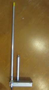
Here is a picture of my Dipole (In its in-completed state). It’s simple as it gets. Two wires cut at around 8ft each insulted by some sawcut plexiglass and a chassis mount SO-239 Connector.

Since I didn’t want to run it outside hoping that I get my Butternut installed, I placed the 10M dipole up in the attic connected to already ran RG58 with a Coax Choke at the end. Thinking I wouldn’t get anywhere with this antenna I was very surprised when I turned on the rig to hear stations in South America coming in . Considering my house is wrapped in Aluminum siding, I am really surprised. So if there are any tech licenses out here. It doesn’t take much to make DX contacts on the tech portion of 10M.

Here are some of the contacts I made in the Past couple of days

CO6CAC – Cuba
ZB2B – Gibraltar
IZ5HPQ – Italy
OE6CEG – Austria
EI8GS – Ireland
MM0BQN – Scottland
PI4DX – Netherlands
S53EO – Slovenia
PY4ZUN – Brazil
LU1ALF – Argentina

All these countries and more from a Dipole in my attic surrounded by aluminum siding! So please get on the Air!

Another great accomplishment is that I Finally got to work a station in Japan! That was a goal I’ve been wanted to do in the past two years.  With the conditions and propagation that we’ve been seeing, It was possible. Got to work JI1RXQ in Koga, Ibaraki, Japan. It was during the JARTS contest so it was a quick contact but I’m still grateful.

Also please stay tuned as I’m updating a lot of the Articles and adding a new completed homebrew project!

Homebrew GMRS 3 Element Yagi

Since I’ve built a ton of J-Poles and wire Antennas, I’ve wanted to build something different. I decided on a 3 element YAGI built for GMRS that is directly fed with 50ohm coax. After a couple of failed yagis and the help of another ham on QRZ.com forums, I finally built a Yagi that works! The reason I’ve chosen a Yagi built for GMRS is due to the ultra high frequency, which ends up being a small antenna. If I were to mess up (Which I did), the material cost would be low. I also wanted to use it on a GMRS repeater in the area.

The first Design I used is with a Web Site that has a Java base applet to design the Yagi, After getting all the Dimensions from the website, I went to work building the antenna. After everything was done, I learned two things. One is that my drill press does not drill straight (90 Degrees) through the tubing. The other thing is that when I hooked up the antenna to a simple SWR Meter, That didn’t work either (Pegged the Meter). At this point I got frustrated  and posted my issue on QRZ.com. A Ham by the call of WB3BEL (Harry) took my dimensions (That I got from the applet) and plotted my antenna into 4NEC2 software (Like EZNEC but freeware) and it would not work for the center frequency of the GMRS Band (or any part of the GMRS band).
WB3BEL actually re-designed the antenna to where it would work so I give him credit and major thanks for help. I took his Dimensions, Modeled the antenna for fabrication and built the antenna. I Hooked up the antenna to a transceiver and SWR meter and got a 1.2:1 SWR and a 1.5:1 SWR on the outsides of the GMRS band. The Design is calculated to yield 7.5Dbi of Gain. Considering connector and cable loss (Lets say 4Dbi using 50ft RG-213 W/ 3 SO-259 Ends and a Barrel Connector) still yields gain of around 3.5Dbi which is not too bad.

Here is rendered Image of the Antenna. The elements are Insulated from the boom using plastic shoulder washers for the Reflector and director. The Driven Element is insulated using a 0.750(OD)X.375(ID)X1.5″(L) Plastic spacer. Since the elements are going THROUGH the boom, It will make the elements electrically shorter so you have to compensate for the loss by adding 0.279528″ (7.1mm) to the element to correct the effect (Boom correction). The elements are secured using #8-32 Screws screwed to the boom. The screws are also insulated from touching the boom. The screws do not make any significant changes to radiation pattern of the antenna as long as it’s insulated from (not touching) the boom. I did notice that the screws actually lowered the SWR a tad which is great.

I didn’t add a matching network to the antenna because I wanted an easy to build and assemble antenna which is the entire point of this article. The antenna is fed using RG-213 Coax with terminals soldered to the core and shield. I tried to keep everything as short as possible because this and the ring terminals effect the performance and SWR of the antenna.

Here are a couple of screen shots from the antenna software that show the Radiation Pattern and gain. Nothing special here.


Here is the calculated results for the SWR of this Yagi. Please note that it’s in the ball park. By adding screws, coax leads and the ring terminals, it could or will effect the final pattern and/or performance of the antenna.


Here is a SWR Shot. As you can see, I don’t have a very good meter. I would like to buy a HF/VHF/UHF Antenna analyzer for my Antenna builds but I don’t think that will happen in the near future.


Here is the complete Antenna.
Overall it was a fun little project. It took a short time to build and it’s a great directional antenna with some gain to help your signal on GMRS reach its destination.

Continue reading if you want to build this antenna.

Continue reading “Homebrew GMRS 3 Element Yagi”

HCRA Field Day 2011

This year I participated in Field Day with the Hampden County Radio Association. Instead of dropping by a site and using their equipment, I decided to offer up my equipment for use as the “HF DIGITAL” station. Other than a couple of software issues, the Digital station was a success with over 170 contacts.

Here are the pictures I’ve taken from Field Day

Check out Hampden County Radio Association’s Website for information about Field Day.
Continue reading “HCRA Field Day 2011”

OSJ-Pole – Adjustable

The thing that amazes me about the Open Stub J-Pole is it’s simple design that performs well. I am not saying it will out-perform commercially built high-gain antennas but that it performs well using a few parts. I think it’s even easier than building a copper J-pole and even ground plane antennas (maybe just a step up).

One of the big complaints that I’ve been reading about the Open Stub J-Pole is that it’s difficult to tune. The only way to tune the antenna is to actually cut the stubs a little bit at a time. If you cut too much the stub is now worth it’s weight in scrap.

Now that I am the owner of a GMRS radio, I wanted to build a OSJ-Pole that you can adjust with ease. I found plans on the internet for a  Copper Cactus J-Pole that used a brass screw threaded into the “Tuning element”, or the Short stub (By Glynn Rogers, K4ABT).   I am using that idea on the OSJ-Pole. What I ended up doing is cutting about 3/8″ off the top of the short stub, drilling a hole down the center of the rod, tapped it with a 10-32 thread and inserting a screw with a jam nut. Now I can move the screw in and out to obtain the best SWR and then tightening the jam nut to secure the screw.

Here is a picture of what I am talking about

Adjustable Open Stub J-Pole

I tried to make a custom angle bracket with what I thought was the correct spacing  but the SWR was horrible So I used a extra bracket from one of the many Dual Band OSJ-Poles I’ve built. It worked out pretty well.

Close up of "AOSJ-Pole"

Here is a close up of the tuning screw.  I ended up using a lathe and a drill bit (.159) to put a 2″ hole at the end of the 3/8″ round short element. I then used a bottoming tap to make the 10-32 threads as far as I can go. I then used a 1-1/2″ Screw and a 10-32 Jam nut to lock the screw in place. I am sure this can be applied to any of the Open Stub J-poles that are out there. Just make sure to cut some material off the elements so you have room to adjust above and below the calculated line. For the dual band you’ll have two adjusters. Since most people don’t have lathe access to make the hole in the center of the 3/8″ rod. A vice, center punch (automatic or not) and a steady hand with a drill will do. I would make a pilot hole with the smallest drill bit in your stock (under #21 or .159″).

I was able to tune the AOSJ-Pole from a 1.5 to a 1.0.  Since I am building more and more antennas, I saving my pennies to buy a antenna analyzer so I can give better reports with more information than what I am getting on my SWR meter.

Next project will be a GMRS 4 Element Yagi.