SOTA Activation Report: Bare Mountain, Amherst MA (W1/CR-014)

The KX3 isn’t getting much use as I would like. So far I only used it one other time this year while camping in Vermont. I need to get out more so I took advantage of mild day and decided to go out and activate a local mountain. I decided on Bare Mountain located on the Amherst, South Hadley and Granby border here in Western Mass.

20150810_185914

Mt Holyoke Range State park had two SOTA summits on the property. I’ve chosen Bare over Mt. Norwottuck because it’s a faster hike even though it’s more rocky. It allowed me to get up the mountain with time to spare to setup the antennas

Bare mountain is approx 1018ft (309m) height in elevation

The Hike

Since I haven’t done any hiking in a long time, the hike up was not great. I was huffing and puffing. The last time I did Bare Mountain, it was covered with snow and ice. I can tell I am out of shape because I felt I hiked up much faster in the wintertime even with the trying to navigate through ice. I really need to get out. I managed to make the

20150810_192625

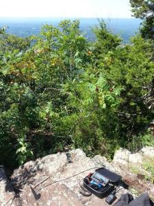
View of the CT river from my operating position.

Track

APRS Track of my activation. I used the Internet Gateway along with my phone to let people know I am at least moving around.

Getting on the air.

Soon as stopped huffing and puffing, I was up and running within a few minutes. I currently use an Elecraft KX3 with the internal Antenna Match, internal batteries and for the antenna I use a G5RV jr supported by a 31ft fiberglass pole. The antenna is setup in an invert V configurations. I secured the ends of the antennas to near-by trees using bungee cords.  The mast was also secured to a smaller tree with elastic cord as well. It allows for a quick setup and everything breaks down to fit into my pack with the exception of the mast that I use as a walking stick.

20150810_193605

Once the stations was setup, I found what I thought was a clear frequency and posted it up on SOTAwatch. Sure enough, soon as I sent the spot, someone came on frequency. My QRP signal was not going to compete with a DX station constantly going “Ooooola, OOooooooola”. After a couple more frequencies, I found a nice spot and went on the air.

Here is a video I made of my SOTA experiance.

Contacts Made

Time Freq Callsign Sent Rcvd Notes
23:48 14.307 K4MF 59 56 FL
23:49 14.307 KC5CW 59 57.TX
23:50 14.307 NG6R 59 43 CA
23:50 14.307 K1MAZ 59 59 MA
23:50 14.307 KK1W 59 59 MA
23:51 14.307 KK4ASA 59 59 MA
23:52 14.307 K5IIK 59 59 AR
23:55 7.198 KF7MQZ 59 59 NY
23:57 7.198 K2JB 59 59 NC
23:57 7.198 WW1X 59 57 GA

Since it’s 0:00z, it’s considered a new day so people get to work me again for an additonal point. However I won’t get credit for it since technically I already activated it the day before even though it was only a couple of minutes.

Time Freq Callsign Sent Rcvd Notes
00:01 7.198 KK1W 59 55 MA
00:01 7.198 WW1X 59 57 GA
00:02 7.198 K2JB 57 59 NC
00:02 7.198 K1MAZ 55 55 MA
00:03 14.307 KC5CW 59 44 TX
00:04 14.307 K4MF 59 57 FL
00:04 14.307 NG6R 59 32 CA
00:05 14.307 KG5EIU 57 33 TX
00:10 146.520 N1FTP 59 58 MA
00:11 146.520 N1TA 59 59 MA
00:15 146.520 N1IVT 59 59 MA
00:16 146.520 N1FDC 59 59 MA

Not too bad. This was all using AA’s in the KX3 so the power was around 5W. I started getting battery low alarms towards the end of my activation. I’ve since “blew up” my lipo pack so if I keep doing activations, I will get my hands on a battery pack so I can run up to a whopping 12 watts.

Hike Down

20150810_203432

View of Hadley, Amherst and UMASS from the summit

There was twilight on top of the summit made me think I can navigate down the mountain before it gets too dark. I was very wrong due to the thick amount of trees that blocked out any possible light. I was almost pitch black with the exception of the street lights at the base of the mountain. However I knew this was possible and packed flashlights and headlamps that made the hike enjoyable. I also used my cheapie HT to talk to locals on the repeater that made the hike feel much faster.

Overall thoughts

I always to learn from anything I do. I’ve learned that I need to get out more (doi!) but I also see the importance of a “Go Bag”. I often don’t plan my SOTA adventures until the last second. Because of other vacations and other portable operations, all my gear was spread around in different places. I’m going to purchase a dedicated pack just for summits on the air. I’m not going to make the typical whacker go-box. I like to pack minimal so it will be just what I need to get on the air. I don’t need the kitchen sink. Funny thing is that I tend to make more QSO’s with the less gear I bring. However self spotting on SOTAwatch does make things a lot easier. I still want to try a SOTA activation without advertising it. I had an excellent time like usual.

Thanks for reading. Hope you like the youtube video.

– Jeff NT1K

My Mountain Topper Radio project

After doing some portable operations with the KX3, I felt that having something smaller and lighter would allow my pack to get smaller and smaller. The only problem is that there is nothing smaller than the KX3 that is comparable unless you get a CW only rig. I decided to get the MTR (Mountain Topper Radio) that was developed by Steve Weber (KD1JV). It’s a 2.5-5W QRP CW rig that gives you the options for two bands.

The problem is that the MTR kits are produced and sold in small quantities with high demand.  I’ve learned that Steve developed a version 2 of the MTR (3 bands) and had a pre-sale. Even though he gave out the wrong URL, people managed to figure out the correct URL and sold out within hours. I found out a tad too late and ended up having my money refunded.

I was a little bummed out. I was very excited that I might get this kit. I’ve never worked with surface mount devices and the CW only aspect of the rig would sort of force me to actually learn CW. After making my disappointment known, a local ham mentioned that he had an unbuilt kit from the orginal run that he might be willing to sell to me. Making fun of him didn’t help but I think the fact that I might learn CW might have compelled him to sell me his kit.

What did I just do?

Once I got my hands on the kit and took it home I inspected it (what ham doesn’t when they get a new toy?). That’s when I saw the components I’ll be dealing with. Very tiny resistors, capacitors and IC’s. The toroids were tiny and were not wounded.  Everything is so… small. I have built ham radio related kits before but they were all through hole meaning that the parts like the resistors and IC’s had legs and pins the fit into the holes. They were large enough to where I can easily work with them.

I am not prepared for surface mount work. My soldering iron is this $10 Radio Shack 35W fixed iron. I knew it was not ideal for SMT as I have tried and failed using that iron. I need to learn how to solder surface mount and I need the proper gear to do it with. I’ve learned over the years that working with the correct tools makes the job much easier.

New Tools In The Shack

I’ve learned the hard way many times over that having the proper tools can make things a lot easier. I feel that I have everything needed for the job except for a soldering iron. I looking at the sub $40 Chinese type irons but I stopped myself from purchasing one. I wanted an iron that can last me for many years so I ended up purchasing a Hakko 888D soldering iron. At around $100 I felt that it was worth the purchase.

The Build. Day One!

Soon as I got the iron in, I went straight to work. Following the assembly guide I started with the IC’s and the MCU. I felt that you are starting with the hardest part of the job by soldering small SMT IC chips with small leads and small gaps. I avoided installing the MCU and DDS chips until the other ICs were installed.  Once all the IC’s were installed, I used a jewelers loop and checked my connections. The MCU was crooked a bit and thought it was still good so I kept chugging along. I installed the resistors on the bottom of the board and called it a night.

20140506_215401

My working area. You’ll see the board with solder, tweezers, assembly manual, solder, 10X  Jewelers loop, desk lamp with magnifying glass and my new soldering iron. When I purchased the soldering iron, I also purchased different sized and shaped tips.

The Build. Day Two

Next day I got back from work and installed everything else.  It wasn’t really bad as I thought. The soldering Iron was tight in some places but it appeared everything went quite well.

smttsd

Here is a close up of my soldering. It could be better but I would say not too bad considering I’ve never done SMT work before.

Power On Time.

I didn’t want to wire up the power, headphones or anything else because I was going to design a case but in order to make sure it worked. I needed to wire it up.  Soon as I hooked up the battery… Nothing!  It did’t lite up, It didn’t beep. The only thing I notice was a slight noise in the headphones. Sounded like the noise of when you turn something on.

What Went Wrong?

As panic starts to set in, I was worried that I now have a nice new expensive brick  on my hands. All that time, energy and money spent on the kit and tools needed seemed be wasted. Out came the jewelers loop and soldering iron. I double checked every connection. Then I took out the multimeter and followed the troubleshooting guide in the manual and started checking voltages coming out of the regulators. Everything was checking out. The only thing I see is that the MCU was a little bit crooked.

I tried re-soldering the MCU but it proved to be very difficult. I used solder wick and suction tools that did not help, the chip would not move for me. For me the only choice was to remove the MCU. But how? After some internet searching I decided to use enameled wire and snake it under the chip where the leads meet the chip. I then touched the soldering iron to the leads and slowly pulled the chip off.

eIpMXvS

Using that method allowed to me to remove the chip, but in the process I damaged the MCU. The above images is not representative of my soldering work. It was more of a panic move and I just wanted to get the chip off without damaging the pads or board. The pads were in great shape and I’m just lucky nothing else happened.

Dealing With Steve Weber

Well it’s obvious the chip will need to be replaced. There are two options available. Beg steve for a new chip or purchase the MCU and flash it using a MSP Launchpad. I almost went the latter because Steve just released V2 and I am sure he was busy dealing with that and life in general but I decided to e-mail him anyways.

Dealing with Steve was a pleasure. I know these radios is not his full time job but he replied within a reasonable time and he was willing to send out a pre-programmed chip for my version of the MTR. Since I was having him sending me stuff, I purchased a case because the price he was asking was more than fair.

Attempt #2

Now that I have the new MCU, I promptly installed it. This time I quadruple check to make sure the chip was aligned properly before soldering. It went much better.

9xY2xy6

When I applied power I jumped for Joy as I saw the LED come to life and the sounds of CW in my headphone. I did some initial testing and then installed the last toroid.

It’s… ALIVE!!! ALIVE!!!  

Now that it turns on, it’s time to make the adjustments needed for proper operation. Thankfully I have Acquired the test gear I needed over the years from mostly local hams looking to clean their shack. I have a decent frequency counter, oscilloscope and a station monitor.

The manual found on the Yahoo Groups page provided step by step installation and tuning. It made things a lot easier.

20140525_093919

First thing I did was adjusted the reference oscillator frequency to match exactly 10MHz. This was very easy. Just pushing a button until I see 10Mhz on the counter. There are reference points on the board to where you can easily measure things.

20140525_094159

Adjusting the LO to find the center of the passband. This was a little tricky because I didn’t fully understand the manual and process. In the tuning mode the MCU sends out a tone and I adjusted it by watching the signal peaking on my scope while counting the steps between the peaks. I then went backwards only half of the steps. Hopefully it was done correctly. For me, this was the hardest part of tuning.

20140525_095042

Here I am adjusting the receivers filters. With the station monitor I injected a signal into the MTR through the antenna port and adjust the band capacitors until the signal was at it’s loudest. I did the same thing on the other band. This was quite easy.

Last thing I did was hooked it up to a dummy load and checked for output wattage. Using a variable power supply and a DMM hooked in-line, I’ve sent out a tuning signal and adjusted the power supply until the DMM read 9Vdc with a TX load. I was seeing approx 2.5W which is within spec.

Time to get one the air

Now that it’s built and tested, It’s time to get on the air and see what I can (not) do.

20140525_100322

Heh, it’s smaller than my paddle.  What’s great about CW is that you don’t have to call CQ over and over again hoping someone would come back to give you a signal report. Just call CQ a couple times and head over to the Reverse Beacon Network where you can see almost in real time where your signal is being heard. There are receivers all over the world scanning the bands for signals.

TdHhvUi

Here are my results using just a crappy 9V battery. I am pleased to see that not only are stations hearing my signal, but they are on the frequencies that the MTR is tuned to. While I was testing the worst thing happened… Someone replied. I tried very much to work the person. I know the call was a K2 something but that’s all I could make out.

Final Thoughts

This was my first actual kit that I built, It’s also the first time that I ever worked with tiny surface mount devices and even though I messed up the MCU, it was really fun to build. Soldering SMD seems to be a nightmare but after the first couple of parts, it felt real easy and it felt that I was working much quicker compared to through hole parts. This project is also a big kick in the ass to learn CW because I want to use this rig. I’m all about packing very lite when it comes to SOTA and even though I love the KX3, I feel it would be more of an adventure using the MTR. We’ll see.

Thanks for reading!

– Jeff


Elecraft KX3 – What Did I Just Do?

I’ll be honest and say that I laughed when I saw the Yaesu FT-817 for the first time when it was released in 2001. “You’re not going to make any contact with that! It’s small and only 5 watts! No one is going to hear you!” I recall saying a lot. I like to note that I was brand new to amateur radio and had no HF experience. I thought it was silly to “talk” around the world with the same amount of power that my handheld VHF puts out. Well… 12 years later and they are still being produced and sold. I’ve seen the error of my ways and accept that QRP (low power) contacts are very possible. Now that I’ve been involved with HF for about 4 years now, I can see how rewarding QRP contacts are. Now that  I’m more involved with SOTA (summits on the air), doing a bunch of VHF SOTA activations and watching my peers on HF, I decided to purchase a portable HF rig.

I ended up going with the Elecraft KX3.

I could have went with the much cheaper FT-817 and other QRP Xceivers but the features and technology of the KX3 far surpass what the FT-817 had to offer. Well… at least in writing. I just wanted something NEW for a change. Even though the KX3 is expensive, I cheaped out as much as possible and got the kit version of the KX3 with no options or extra accessories.

20130313_162521


Hopefully the postal carrier didn’t notice me peeking through the windows with the excited look on my face as he approached.

There are already dozens, if not hundreds of videos, blogs, forum posts of assembling the KX3. I am not going to go into detail here. However I would like to share some notes and tips if you were to get the kit. Most are common sense.

  • Spend time and make sure every nut, screw, standoff and part is in the kit! Use muffin tins or a tackle box to keep parts separate.
  • Do not be surprised if your missing something. They include an extra parts bag and hopefully it’s in there.
  • Read the assembly manual entirely before starting. Do not jump ahead!
  • It’s not a contest, take your time and confirm each step

20130313_163024

Besides a screw driver and other basic hand tools. I strongly suggest in using tweezers or a “Jewelers Pickup Tool”

pickuptool


This tool helped me out as the tiny 2-56 screws were  a wee bit hard to handle.

The only issues I had were installing the plastic battery holders (which is noted in the manual) and having to deal with missing 4-40 screws. luckily I had anodized screws in my personal extra screw bin. Overall the assembly went okay and it took about 2 hours.  Is it worth the extra $100 for an assembled kit? All depends on how you value your time. Think of it costing $50/hr for assembly. Are you worth more than that?

First thoughts

887314_10200346981013640_1625377524_o

After turning it on, one of the first things I did was to compare the receivers of the KX3 to my FT-950 using a switch and the G5RV antenna. Since I don’t have any type of equipment that will give accurate readings, I am basing my findings from what I’ve seen and heard. On SSB, it seemed to receive similar with the DSP turned on in the 950 (No DNR). It has similar S-Unit readings. However the KX3 felt like it dealt with adjacent signals better than the 950. On CW, it seemed the KX3 was better at receiving.

Should Have Purchased Options

Like usual, I was being cheap and purchased the KX3 as a kit without any options. For some people that would work just fine. If you have a spare microphone and resonate antennas at the frequencies you want then you might not have a need for options like the ATU (Automatic Antenna Tuner) or microphone. But here I am with no microphones and no resonate antennas. I could have purchased an Emtech ZM2 or Hendricks SOTA tuner and a used microphone online that would have done just fine, but I didn’t want to lug around more equipment and didn’t want to modify the microphone. I ended up purchasing the ATU  and Microphone from elecraft a short time later.

Issues with the KX3

I’ve held off writing this article for a long time because I had issues with my KX3. After assembly and before installing the ATU, I was hot to trot. I went on the air, started sending out CW to see what skimmers (bots) were picking up my signal. I couldn’t transmit at full power. Even with the KX3 powered using an External 5amp supply, I could not get past 7W. When using batteries, I saw 3watts max.  Putting blame on my antenna at first I didn’t think much of it. At this point I decided it was best to order the ATU as I would end up using compromised antennas like an end fed or random wire where needing a “tuner” (match) would be important.  When I received and installed the ATU, I noticed that I couldn’t tune correctly and it was still folding back power. After taking it out on it’s first SOTA activation, I knew something was wrong.

Dealing with Elecraft

I knew it had to be fixed. The first stop was the Elecraft KX3 Yahoo Group to see if anyone else had similar issue. None were found so after following the advice on Elecraft’s website, as requested, I contacted them VIA e-mail.

I’ve heard that Elecraft support was AMAZING!!  However I felt the opposite. Just to get a reply from Elecraft took me well over a week. I ended up finding e-mail addresses to some of the staff/support members for Elecraft and after contacting them, my issue was finally looked at. It felt like I had to be pushy and demanding to get stuff done which is not a part of who I am so it was uncomfortable. However I just spent a lot of money, for some it may be nothing but it was a lot of saving on my part  so I felt cheated a bit even though Elecraft did absolutely nothing wrong.

Once the RMA process started, it was fast and easy. Elecraft sent me a confirmation once the item was received but I didn’t hear anything else until the day it was shipping out almost a week later. Since I’ve never dealt with returning a radio before, I felt that I had no idea what was going on or even if the radio has been touched by service. When Elecraft got back to me, it was shown that the PA Driver chips were replaced. I wished for a little more detail into what could possibly caused the replacement as to avoid it from happening again.

Months later and with very LITTLE use, the plastic knobs started to crack. After contacting Elecraft, they moved quick and got the replacements I need. Even though it appears this was a common issue, I was a little more impressed with their service this time around.

Amplifier over 2M module 

When the KX3  first rolled out, a 2M module was incorporated into the design but wasn’t available. Due to the fact that I enjoy doing SOTA on VHF, I was excited that there was going to be a 2M option at some point. That means less equipment that I’d have to carry and something better than the Chinese radios that I’ve been using.  However I was very disappointed when they decided to design an amplifier for a radio that was designed to be a QRP portable rig. I get why they did it. Not many people really care about QRP SSB on 2m or 2M in general when it comes to portable operations. They would rather have something that would allow for 100W while mobile or at the home while taking advantage of a really good receiver. It turns the KX3 into a dual purpose rig. I would have rather seen the 2M module first.

Even though at times, it may seem I’m very critical of  Elecraft, It’s because I want them to succeed.  They make good products, they’re very interactive with the community and they’re based in the United States. I just want them to improve so they can be on the same production level as the “Big Three”. I honestly think it’s possible.

Final Thoughts

1147772_10201190346617253_338388934_o

Using the KX3 on top of Mt. Tom, Holyoke MA

When I decided to purchase the KX3, I thought I would be taking up adventures  like climbing mountains, hiking, going to parks and testing the limits of QRP. It  didn’t really happen. Those times I got to get out and played radio, the KX3 performed very well. The very low current draw allowed me to use full power (approx 10W) using a Hobby battery (Turnigy 2200mAh 3S 20C Li-Po 11.1v) that lasted for at least an hour before turning back the wattage (to 5W) when the battery voltage dipped below the 11vdc threshold (time will vary depending on duty, temp and mode).  The radio is easy to pack and deploy. If there are trees tall enough in the area, I can hang a dipole and get on the air within 10-15 minutes.

Even though there are cheaper alternatives, I think I’ve  made a wise choice. If I ever decide to go portable, It’s there  and ready to go and it just works.

CYELTh4

SOTA Pack consisting of KX3, G5RV Jr and End Fed

I would recommend this radio to others under certain circumstances. If you’re just getting into the hobby, I wouldn’t suggest it unless you have the money for radio and amplifier or you live in a restricted area where a base antenna setup is just not possible and would have to go portable/mobile. QRP is a rewarding challenge but frustration will set in when your in a pile up with a 5W signal and a compromised antenna.

Hopefully the 2M module doesn’t cost as much as the K3’s module.

Thanks for reading!

The NT1K Webcam Is Now Active!

You can now visit the NT1K Webcam here.

I’ve  decided to add a webcam to the NT1K shack and it will be broadcasting whenever I’m on the air for an extended period of time.  The audio will be fed from the radio so you can hear whats going  on the Air.  It’s the best  choice since I mainly use headphones while on the radio. The camera will either be focused on the shack itself or the front panel of my radio so you can see what  freq I am on and possibly see  how well you come across my station.


Live stream by Ustream

Press the play button. If  it says “Recorded Live” that means I’m not live and you’re seeing/hearing a past QSO.
If I happen to remember, hopefully you will see QSO’s with DX stations

Custom 19″ Cabinet for a portable repeater.

This project is more related to sheet metal design than Ham Radio because the fact that it could be used for more than just radios.

A friend/fellow operator asked me if I can build a 19″ rack mount for a portable repeater. I’ve learned over the years to NOT volunteer my time and/or services because it can lead to a lot of trouble and out-of-pocket expenses. But I owed it to him and I actually always wanted to design a desktop rack mount. Since time is of no worry, I felt comfortable working on this project.

For those who don’t know what a “19 Inch Rack Mount” is. It’s a standardized frame or cabinet/enclose for mounting equipment modules (i.e computers, radios, telecom equipment, and etc). These modules have a front plate that is 19″ wide which have holes/cut outs to allow the module to be mounted to the frame that has a standardized pattern. Since it’s a (EIA) standard in the industry, designers and fabricators have the basic foundation to design their product off of.  There is also a 23″ rack but the 19″ dominates the market at this point in time.

Having a standardized system makes the design aspect a lot easier to tackle. All I really had to figure out were the dimensions of the Motorola CM series radios.
Once I had that, It was actually quite easy to design.

I’ve personally dealt with these type of racks in fabrication, but I have never had a chance to actually design something using this standard. Hence the main reason I am making a this cabinet.  I’ve learned quite a lot from this project that will make me look just a little harder when it comes to similar projects.

Here are some pictures of the project.

Here is the 3D rendering of what I designed. On a lot of my projects that involves showing the image of the render before fabrication, I added a dollar bill to the project as a reference to size. It actually took about a couple of hours over a span of 3-5 months to design.

The laser doing it’s job. It’s about to cut on the front panels

Here is everything after laser cut in the flat. Little bit of deburring to take off any dross/slag  and off to the bender!


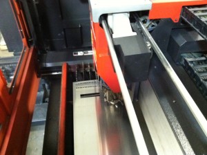
I wasn’t able to snap a picture of the machine actually bending up the cabinet but this is the machine that did it. It’s called a Panel Bender and works great for projects like this. The tooling is already installed and all you do is punch in a couple of numbers and off to the races. With this project and the time constraints, I bent every part by eye without using the CNC gauging system (takes longer to program the machine). I knew I was going to bend by eye so when I programed the part for laser cutting, I added little cutouts to physically show where I am going to place a bend. Line up the little cutouts with the tooling on the machine and it will put the bend within the tolerance that I need for assembly.

Here is the box after bending. I did a test fit by assembling all the parts. In the design I added 1/8″ diameter alignment holes. These holes when lined up and used with cleco pins (sort of like removable rivets) , will temporarily hold the panels together. This will allow me to either weld, spot weld or take one cleco pin out at time and replace it with an actual rivet.

Here it is all assembled and ready for paint. I decided on a black texture powder coat because it’s used often in the industry. Plus it hides my fat greasy fingerprints quite well.

And there she is… Ain’t  that a thing of beauty? I placed a 2U power strip just to illustrate that how universal it can be. Well that’s basically it. This little article is to show to process from the thought to design and from design to build. If I were to even build something like this, I would use thicker material and stick to the specs on the standard a little more closely. I would also add handles and reinforce the area where the handles are mounted.

Edit (9/30/2011): Here are some more photos (Click to enlarge)

Here is it at the house…

Here is a different view. On the bottom of the unit is a surge strip. When I fabricated I only made 3U panels so if I were to install devices that took up 1u or 2u then I would have a gap. So I made some additonal panels which haven’t been painted

Here is a upclose  shot that will show how the panels or modules are mounted. Depending on the design, some rack systems have sliding frame rails to extra weight support. The silver looking thing you see is actually a spring clip with a floating #10-32 nut. Back when these racks were first being designed, instead of using a square hole with a captive nut, they just had regular round holes that were drilled and tapped. Problem was if the threaded hole were to become stripped due to major use or misalignment, then the entire unit could be scrapped if it couldn’t be repaired. With the new system, you can just pop in a nut where ever there is one needed. If it gets stripped, just replace the nut!

Here a picture of the back of the unit. I created a 2X3″ in opening to allow cables to be routed through. When not in use, the gasket-ed cover can bolt right into place using two #10-32 screws that screw into pressed inserts on the main body to create a nice air/weather tight fit (even though the rest of the unit is not air tight).


Here it is with the radios installed. Considering this is the first time I actually got to physically handle the radios, everything lined up okay considering I was using the specs from a similar radio for it’s dimensions.

Overall it was a great build, I just might build another one and apply what I’ve learned on the new box If by some chance you have the chance to fabricate something similar, I would use 1/8″ Aluminum or 12ga (.105″) steel.


New Radio (Hand Held) – Wouxun KG-UVD1P

Wouxun KG-UVD1P
New Radio

Today I gave my self a Christmas present.   Before this purchase I did not own a working VHF/UHF Radio. I have a Kenwood TH-78a that I love. It just needs a new battery pack to get me going. I went out following a snow storm and drove 40mi to Lentini Communcations in Berlin CT. which is my nearest “HAM” radio store and purchased the WOUXUN KG-UVD1P Dual Band  (144/440) Transceiver. I was a bit skeptical about buying a Chinese branded ham radio that is not one of the big three (Yaesu, Kenwood and ICOM), but I figured the price is right ($130 w/ programing cable) and QST magazine gave it a good review.

First impression was not bad. The box looks nice and everything was neatly packaged. If I were to be over critical, I would say that the programing/usb driver CD’s should be regular sized instead of the Mini-CD that was given to me. I like that the battery is fully charged and it includes a drop in charger which I think should be a standard with any handheld that is purchased.  The manual just gives the basics and has a lot of engrish so for those who depend on reading a manual rather than trial and error to operate a radio will find it a tad difficult to follow. You can also tell the radio is designed for general public use and not for amateur radio but that doesn’t phase me considering I’ve owned Motorola radios which I think they are harder to program.
After attaching the battery pack and the antenna, I powered on the unit to hear a voice speaking to me. It took me around 5min to look around, input a frequency, input a tone, set the offset, assign a offset and start talking on a  repeater 50 Miles away. I wasn’t crystal clear but I can hear the other station and the other station could make me out.

I am going to start off with the cons

CONS
– Antenna connection is reversed (SMA FEMALE ON THE ANTENNA, SMA MALE ON THE RADIO)
– Not true Dual VFO. You can monitor two freq’s but locks out the other on activity.
– Hard to program through keypad
– S-Meter doesn’t seem accurate. I was barley getting a repeater and the S-Meter was showing full bars
– Can’t program both side keys

PROS
– PRICE PRICE PRICE!!! $130.00 US for everything
– Desktop Charger!
– Great receive
– Great Transmit
– Long lasting battery (7.4v 1300 mAh Li-Ion)
– Decent Size  (2-1/4″ Wide X  4-1/8″ Tall X 1-1/2″ Thick)

As of right now I would recommend this to anyone. However I strongly suggest if you purchase this radio to also get the programing cable and software (you can download the software from their website) .

My FT-950

FT-950

Ain’t it a thing of beauty? heh…

Before I upgraded to general I purchased an FT-857D. I was planning on putting it in my truck but I ended up using it in the house since it was my only HF rig. I wanted a bigger system so I could put the 857D mobile and I ended up getting a Kenwood TS-430s. After making  the impulse purchase I realized that the TS-430S is not suited for digital. I kept using the FT-857D as a home unit and then I decided to sell everything for a new HF base that could handle digital. I was debating between the Kenwood TS-2000 or the Yaesu FT-950. For reasons which are unknown I ended up getting the FT-950. I am loosing VHF and UHF by getting the FT-950 But I think I made a wise purchase. So far I am loving this rig, it’s taking some getting used to but it’s amazing how a couple of adjustments makes a someone who I can barely hear sound like S9.