CQWW CW Contest / Rants

I decided to participate in CQ Magazine’s World Wide CW (Morse Code) contest. It’s one of the, If not the biggest CW contest of the year.
I have been trying to learn CW off and on since the summer so I needed some help if I were to even make one QSO on CW. I setup N1MM logging software for the contest and used DM-780 that comes with Ham Radio Deluxe to decode and encode the CW.
Since I never participated in a CW contest before I wanted to see how it worked so I can configure my macros to work with the contest. I was very impressed on how fast contacts and exchanges are made. It’s way faster compared to SSB, RTTY and PSK31 and I felt even more compelled to learn CW after playing in this contest. I worked the contest off and on so I wouldn’t get overwhelmed about the activity. I started off searching and pouncing (S&P) on only the strongest signals. I would wait until I have their full call and exchange before even attempting to contact the station. N1MM does help out by looking up the CQ zone which came in handy a couple of times. After establishing contact I would get the typical 599 and zone exchange. After the first night working the contest. I have learned what my new call sounds coming back to me and phrases like “TU”, “TEST”, “?” and some of the shortcuts ops used to make a faster contact like instead of a RST of 599, it will be 5NN and A5 would be zone 15. I went to bed with code buzzing around in my head. I woke up the next day to play again. I’ve managed to make 100 contacts even though I know for a fact that I can make more. I just wanted to see what it was like to play in a CW and I liked it. Nothing like just jumping right in with both feet and absorbing everything. Once you learn the key terms in code the contest went much easier. I would encourage ops who want to learn CW to work in a contest. After learning what some of the stuff sounds like, the only trouble would be on decoding the call sign. I just hope that the people on the other end got my call right.

This now leads me to my rant. I lurk around on a lot of Ham radio related forums and also hear it by ear. I see a lot of people saying something along the lines of “These No-Coders are going to ruin HF” and “Amateur Radio is going to be just like CB” because the FCC dropped the Morse code requirement years after many other countries dropped the requirement. Now all these “Techies” or Technician license holders are upgrading to general and/or extra without passing a Morse code proficiency test.
After spending a couple of years on HF I have not seen much (or any) evidence to support this claim that has been spewing out of the elders mouths for over 4 years now. A lot of the Issues I see have a lot to do with elder hams. For example, when it comes to contacting a DX station I see a lot of things happening. Things like after the DX station acknowledge someone, there are still people trying to crowbar their callsign in because there is a second of silence. I also hear 1KW amps tuning up RIGHT on frequency of the DX station then spew out their call (like we don’t know who you are when you’re 40+ on my meter). Then you got those that see a massive pileup trying to contact the station and when acknowledged, will try to strike up a rag chew session by describing their town and the weather and their medical ailments even though there are 100’s of people waiting. And if the DX working split… FORGET ABOUT IT! They endlessly send their call even though you have a bunch of people telling him that the DX is listening 5KC up. Try listening to the RX Frequency of the DX station working spilt. Wholly crap there are a lot of people who don’t even come close to following the DX code of conduct. I’ve jotted a bunch of these calls down and looked them up on QRZ to find out that a majority of them are elder hams (By the age of their call and station setup).
For a Hobby that is so-called “Dying”, I wouldn’t spend much time complaining about those who are actually trying to stay interested in Ham radio. Not only should you welcome these “No-Coders”, you should thank them for showing interest. Because with that negative attitude you will drive away the young Hams that are genuinely interested and you will see a truly dead hobby. After a couple of years on HF and thousands of contacts, It’s rare that I run into someone around my age (28). I basically think that those who bitch and moan about it are just jealous or feel that they are “A class of their own” because they had to pass a 20wpm (or 5wpm) CW proficiency test. The funny thing is that since I’ve upgraded, I wanted to learn CW more than ever so I can make even more contacts farther away.
This is just my personal opinion, I could be wrong.

NO LONGER N1BMX!

I am no longer known as N1BMX. I am now known as NT1K

I decided to change my callsign from N1BMX to NT1K because I am not involved anymore with BMX (Bicycle Motocross). When people see BMX then see me, they see this huge guy that obviously doesn’t ride bicycles, let alone a 20″ Bicycle. I browse AE7Q’s vanity list quite often and saw N1DE has passed it’s grace period and is up for grabs. I’ve applied for vanities in the past that got dismissed but this time I wanted to change my call for good. So I looked the 2X1 calls and added a call that appears that no one else is applying for. NT1K stuck out to me so I also applied for it.

For those who don’t know how the vanity system works, it is somewhat simple. Continue reading “NO LONGER N1BMX!”

We’re in the killing 10M business… And buisness is a Boomin’

Thanks to the Solar activity. 10m is a BOOMIN’ and I Just had to take part. However my G5RV Dipole does not really work well with my FT-950 and its Internal Antenna “Tuning” Unit. I can go and buy a better external tuner but why bother.  With some 16ft of copper wire you can have a Dipole for 10M. I made just that.

Here is a picture of my Dipole (In its in-completed state). It’s simple as it gets. Two wires cut at around 8ft each insulted by some sawcut plexiglass and a chassis mount SO-239 Connector.

Since I didn’t want to run it outside hoping that I get my Butternut installed, I placed the 10M dipole up in the attic connected to already ran RG58 with a Coax Choke at the end. Thinking I wouldn’t get anywhere with this antenna I was very surprised when I turned on the rig to hear stations in South America coming in . Considering my house is wrapped in Aluminum siding, I am really surprised. So if there are any tech licenses out here. It doesn’t take much to make DX contacts on the tech portion of 10M.

Here are some of the contacts I made in the Past couple of days

CO6CAC – Cuba
ZB2B – Gibraltar
IZ5HPQ – Italy
OE6CEG – Austria
EI8GS – Ireland
MM0BQN – Scottland
PI4DX – Netherlands
S53EO – Slovenia
PY4ZUN – Brazil
LU1ALF – Argentina

All these countries and more from a Dipole in my attic surrounded by aluminum siding! So please get on the Air!

Another great accomplishment is that I Finally got to work a station in Japan! That was a goal I’ve been wanted to do in the past two years.  With the conditions and propagation that we’ve been seeing, It was possible. Got to work JI1RXQ in Koga, Ibaraki, Japan. It was during the JARTS contest so it was a quick contact but I’m still grateful.

Also please stay tuned as I’m updating a lot of the Articles and adding a new completed homebrew project!

Custom 19″ Cabinet for a portable repeater.

This project is more related to sheet metal design than Ham Radio because the fact that it could be used for more than just radios.

A friend/fellow operator asked me if I can build a 19″ rack mount for a portable repeater. I’ve learned over the years to NOT volunteer my time and/or services because it can lead to a lot of trouble and out-of-pocket expenses. But I owed it to him and I actually always wanted to design a desktop rack mount. Since time is of no worry, I felt comfortable working on this project.

For those who don’t know what a “19 Inch Rack Mount” is. It’s a standardized frame or cabinet/enclose for mounting equipment modules (i.e computers, radios, telecom equipment, and etc). These modules have a front plate that is 19″ wide which have holes/cut outs to allow the module to be mounted to the frame that has a standardized pattern. Since it’s a (EIA) standard in the industry, designers and fabricators have the basic foundation to design their product off of.  There is also a 23″ rack but the 19″ dominates the market at this point in time.

Having a standardized system makes the design aspect a lot easier to tackle. All I really had to figure out were the dimensions of the Motorola CM series radios.
Once I had that, It was actually quite easy to design.

I’ve personally dealt with these type of racks in fabrication, but I have never had a chance to actually design something using this standard. Hence the main reason I am making a this cabinet.  I’ve learned quite a lot from this project that will make me look just a little harder when it comes to similar projects.

Here are some pictures of the project.

Here is the 3D rendering of what I designed. On a lot of my projects that involves showing the image of the render before fabrication, I added a dollar bill to the project as a reference to size. It actually took about a couple of hours over a span of 3-5 months to design.

The laser doing it’s job. It’s about to cut on the front panels

Here is everything after laser cut in the flat. Little bit of deburring to take off any dross/slag  and off to the bender!


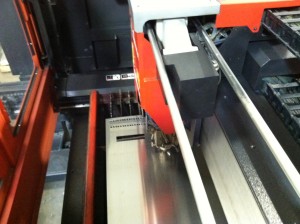
I wasn’t able to snap a picture of the machine actually bending up the cabinet but this is the machine that did it. It’s called a Panel Bender and works great for projects like this. The tooling is already installed and all you do is punch in a couple of numbers and off to the races. With this project and the time constraints, I bent every part by eye without using the CNC gauging system (takes longer to program the machine). I knew I was going to bend by eye so when I programed the part for laser cutting, I added little cutouts to physically show where I am going to place a bend. Line up the little cutouts with the tooling on the machine and it will put the bend within the tolerance that I need for assembly.

Here is the box after bending. I did a test fit by assembling all the parts. In the design I added 1/8″ diameter alignment holes. These holes when lined up and used with cleco pins (sort of like removable rivets) , will temporarily hold the panels together. This will allow me to either weld, spot weld or take one cleco pin out at time and replace it with an actual rivet.

Here it is all assembled and ready for paint. I decided on a black texture powder coat because it’s used often in the industry. Plus it hides my fat greasy fingerprints quite well.

And there she is… Ain’t  that a thing of beauty? I placed a 2U power strip just to illustrate that how universal it can be. Well that’s basically it. This little article is to show to process from the thought to design and from design to build. If I were to even build something like this, I would use thicker material and stick to the specs on the standard a little more closely. I would also add handles and reinforce the area where the handles are mounted.

Edit (9/30/2011): Here are some more photos (Click to enlarge)

Here is it at the house…

Here is a different view. On the bottom of the unit is a surge strip. When I fabricated I only made 3U panels so if I were to install devices that took up 1u or 2u then I would have a gap. So I made some additonal panels which haven’t been painted

Here is a upclose  shot that will show how the panels or modules are mounted. Depending on the design, some rack systems have sliding frame rails to extra weight support. The silver looking thing you see is actually a spring clip with a floating #10-32 nut. Back when these racks were first being designed, instead of using a square hole with a captive nut, they just had regular round holes that were drilled and tapped. Problem was if the threaded hole were to become stripped due to major use or misalignment, then the entire unit could be scrapped if it couldn’t be repaired. With the new system, you can just pop in a nut where ever there is one needed. If it gets stripped, just replace the nut!

Here a picture of the back of the unit. I created a 2X3″ in opening to allow cables to be routed through. When not in use, the gasket-ed cover can bolt right into place using two #10-32 screws that screw into pressed inserts on the main body to create a nice air/weather tight fit (even though the rest of the unit is not air tight).


Here it is with the radios installed. Considering this is the first time I actually got to physically handle the radios, everything lined up okay considering I was using the specs from a similar radio for it’s dimensions.

Overall it was a great build, I just might build another one and apply what I’ve learned on the new box If by some chance you have the chance to fabricate something similar, I would use 1/8″ Aluminum or 12ga (.105″) steel.


Please stop the Noises! STOP!

Ever since I moved to my house I always had noise in my receiver. It wasn’t loud enough for me to care until now. For the past couple of months the noise has been real bad. Bad to the point where I didn’t even go past 20m (14mhz). I Figured when Field day comes around I will be able to see if its something with the radio. I turned on the radio at field day and the noise was still there. I was upset that I was going to have to ship my radio to YAESU for repairs. That is until someone turned off the light that was 3ft near the radio. THE NOISE IS GONE!!! YES!!! Found out that the cheap-o CFL Bulb (or it’s ballast ) was causing the RFI. I thought that this might be the same cause at my QTH. So after field day I setup back home and tried the radio without the lights. Noise was still there. Today I finally got off my ass and started to track down what was causing the RFI. I went to cellar and turned off all the circuit breakers except for the room which the FT-950 is in. The noise is still there. I unplugged everything in the room except the power supply and the Noise was still there. At this point I took a TV car battery (sealed) and hooked it up inside. The noise is GONE! With the process of elimination, I found out that the power supply was to blame. Back when I purchases the FT-100, I Moved the power supply close to the radio so I could power both the radios.

The power supply that was causing the RFI is the SAMLEX SEC-1223. I googled the model number and there were numerous sites that mention the RFI that power supply generates.

Two sites that stick out when it comes to getting rid of the noise are
http://www.n0ss.net/PDF

and

http://www.oz1db.dk/samlex/start_eng.html

ZL2DF used ferrite beads and ceramic disk capacitors  (about US$10 for part modification) placed right before the output terminals  and OZ1DB used two 1.5uf 100V Capacitors ( US$ 3) on the output terminals

HCRA Field Day 2011

This year I participated in Field Day with the Hampden County Radio Association. Instead of dropping by a site and using their equipment, I decided to offer up my equipment for use as the “HF DIGITAL” station. Other than a couple of software issues, the Digital station was a success with over 170 contacts.

Here are the pictures I’ve taken from Field Day

Check out Hampden County Radio Association’s Website for information about Field Day.
Continue reading “HCRA Field Day 2011”

FIELD DAY – 2 Weeks!

I will be participating in Field Day this year with the folks from the Hampden County Radio Assocation ( HCRA ). I’m excited because I will be using my FT-950 as the site’s HF Digital station (Mostly PSK, RTTY). So if you live  or will be in the Western Mass area on the 25th and 26th of June and want to see Field Day up close, we’re going to be at Dufresne Recreation Area in Granby, Massachusetts. All are welcomed, licensed or not.  Please visit the Field Day page on HCRA’s website. Also check out pictures and data from prior years

For those who don’t know about Field Day, It’s basically an event that takes place on the 4th weekend of June to test emergency communications and it’s deployment. Over 30,000 operators across US try to communicate with as many other field day operators as possible. Points are awarded to operators and/or clubs that make contacts and perform other tasks that would allow for more points ( For example: media coverage, getting Non Hams on the air [GOTA], Copying/fowarding messages). Some Hams treat this as  contest even though the ARRL considers it  an exercise. Whatever the case may be, it’s really fun and it can get you out of the house.

I’ve participated in Field Day multiple times at multiple hosts over the years. I’ve had a Digital setup back in 2004 and had a blast. I recall being very busy using digital back then, I hope that it’s even more popular this year compared to 2004 and hope to be more busy making contacts all over HF.

What: ARRL Field Day Hosted By the Hampden County Radios Association
When: Saturday, June 25th, at 14:00 (2pm), untill Sunday, June 26th
Where: Dufresne Recreation Area, Granby MA, 01033
Why: Because it’s fun, social and you get to operate all different type of equipment.

Hope to hear or see you at Field Day!!

Ham Radio… IN 3-D!

Well, Not really.

When it comes to building things for Ham Radio, I shoot for perfection. Down to the point where I will reverse engineer every part in CAD and assemble my project in CAD before I even start building. It has saved my butt many times over and if there are people actually following this blog, you’ll see evidence of my pre-planning. Here are some examples of what I am talking about.


3D Code Key
3D Code Key


This is my dual touch pad code keyer. This took about a couple of hours to make because I was not sure what type of  touch pad I wanted. I wasn’t sure if I were going to user a horizontal or vertical setup. So I ended up going with both. The horizontal brass keys are inlayed into a piece of plexi glass. the vertical keys are insulated from each other using plastic grommets.


3D Code Key - Built
3D Code Key - Built


Here is the actual touch keyer. This project was considered a failure. Everything worked great until you placed the cover over battery/board, which caused some kind of interference and would not allow the “Dah” key to perform well.  I ended up mostly using the horizontal key pads. If I decided to attack this again, the Vertical keys will be omitted.


3D PL-259
3D PL-259
3D SO-239
3D SO-239

Here is something that most, if not, ALL hams have seen. It’s a PL-259 and SO-239 Connector that I reversed for an amplifier project. Once I have enough small parts designed, I will release just the models (Not editable) for others to use in their designs

Butternut HF9V Mount

Here is a Model of a Mount for the ButterNut HF9V.  It’s a 5gal bucket that will be buried then filled with cement and a pipe to sleeve the Antenna. On top of the Bucket will be my Radial plate I designed to attach the ButterNut to.

HF9V Plate
HF9V Plate

Here is the plate ready for Action. I will go into more detail about this setup when I install the ButterNut.


3D Vibroplex Bug
3D Vibroplex Bug


Here is a incomplete Vibroplex Bug. I wanted to see if it was possible to reverse the bug and it was almost successful. Things like my family and obtaining my extra class license push this to the back burner.  I am saving this to learn how to animate using the software. I still think it looks neat.


You might be wondering how I did this (really?). All of these parts were designed using  software called “Autodesk Inventor 2011”. This software is made by the same people who made AutoCAD. AutoCAD is one of the, if not, the most popular software for Computer Aided Drafting (CAD). There is another piece software called “SolidWorks” that I use as well. I find that Inventor separates the Sheet metal modeling from the 3D modeling which is perfect in my trade. These Two pieces of software are the most used software for design and fabrication for a lot of the items that you use today. Most CNC cutting, milling and forming machines uses the files that are generated by this software.  After designing the part in CAD,  it can printed on a blueprint to be giving to the fabricator, and/or the part can be imported into the software that will convert the information into G-Code for the CNC machine. Once the information is loaded and all the settings are correct, the CNC machine can now do it’s job cutting/milling/forming the part. All of the parts are modeled to 1:1 scale. Meaning if the part is a 12X12″ square piece of metal, I modeled it to 12 inches by 12 inches. That way you can see how it looks compared to other stuff.

If your a ham radio operator, 3D modeling software can be beneficial, even if you don’t have access to CNC a machine. From this software you can generate the blueprints and/or files needed (See my OSJ-Pole prints for example) by fabricators to produce your part. Since you already designed it and gave them the information that they need, it could save money in design/programming. I also think it’s more understanding reading a blue print with proper dimensions than someones chicken scratch or MS paint drawing.  My OSJ-Pole print is the most searched and downloaded file on this site because I think how it was presented to the reader.

Referances:
Autodesk Inventor – Software for 3D modeling parts (They have a free trial!)
Solidworks – Software for 3D modeling parts

MasterCAM – Software  used to generate G-Code for different type of CNC machines. (I would not suggest using this software Unless you own and/or know how use the CNC machine your trying to design for)


VE Accreditation – Yeeeep

In April I decided to apply to be a VE with the ARRL VEC. Reason that I want to be a VE is that at some point (after obtaining my extra class license), I would like to help out with testing hams. Sort of a way to give back.

The process of becoming a ARRL VE is actually quite easy. All you need to do is to go to the ARRL VE  Website, Download the manual, Download the application and question form, Read and understand the manual, fill out the application, answer the questions using the manual, either mail or scan to PDF and e-mail the application with the completed questions to the ARRL.  According to the ARRL VEC, they will check your application and answer sheet, make sure you meet the requirements and issue you a certificate and VE badge that must be worn at VE Sessions. They will not tell you how many you got right or wrong and expect a wait time from 3 to 6 weeks. What ARRL does is hold onto the applications so they can print and mail everything at one time. From what I was told is that they print everything towards the end of the month so if you apply around that time, it could be in the next months pool.

After that time hopefully you will get one of these.


So if your part of a VE Team in the Pioneer valley MA and/or Northern Hartford county CT that uses ARRL VEC and need an extra VE. Depending on the schedule, I could help administer tests. Please use my contact page.  At the time I was writing this I passed my element 4 test and now have an extra class license. Once the FCC ULS updates I will tell the ARRL VEC of my upgrade and will carry around my license until I get a sticker or new badge from the ARRL.

Edit (6/15/2011) – I can’t believe how many people are googling for the answers to the VE questionnaire. It’s not really that hard if you think about it. All of the answers are IN the manual. If you’re trying to answer the questions without reading the manual, it’s going to be a lot harder. I also think that some of the questions are worded in a way so you have to think about it and form your answer based on what you thought. It’s not a copy and paste kind of test.

Extra Class… YAY!!

After a couple of weeks studying, I passed the Element 4 test and now have a extra class license

Extra Class
Extra Class

I used many tools to help my get my license.

Ham Radio Study – Android Application (Tango11)
Ham Test Prep (extra) – Iphone
eham.net exams
Gordon West Extra Class Audio Course – Audio CD

I used all 4 of these tools to help get my license.  In my own opinion, Out of the 4 tools, I say that Ham Radio Study for the android is the best phone app for studying. The application is rather buggy (Don’t rotate your screen!) and there are no diagrams to help with questions that use digrams. The reason why I think it’s the best is that if your trying to brute force the questions and answers into your head, this application will help. It will cycle random questions from the pool and keep asking them until you “Mastered” the question till the point where there are no questions left. That will mean that you learned them all.

Ham test prep (extra) for the iPhone is a paid application and it’s useful. What I like about this application is that you can work at one section at a time or create a practice test with or without random questions. This application also shows diagrams and is pretty useful. Another thing I like is that it tracks and show how well your doing in each subelement group. If they were to incorperate the feature that the “Ham radio study” for android has then It would be the ultimate questions preparation application

For when I am driving around I used the gordon west audio CD. I skipped over the stuff involving math because I find it hard to do algebra while driving on the turnpike. What is great about the CD is that he covers the questions and answers while giving you a general reason why. So he is actually teaching you why instead of learning the answers to the questions.

To mix it up a little bit I also used the eham.net’s practice exams.  I knew I was ready when I kept scoring over 80% on these practice exams and the same with any other software/application I used.

Quick thanks to the Western Mass VE Team (WMVET) for their monthly testing. It’s been at the same place for as long as I can remember.

Hopefully that helps and say hello if you happen to catch me in the “EXTRA CLASS” portion of some of the bands.