CQWW CW Contest / Rants

I decided to participate in CQ Magazine’s World Wide CW (Morse Code) contest. It’s one of the, If not the biggest CW contest of the year.
I have been trying to learn CW off and on since the summer so I needed some help if I were to even make one QSO on CW. I setup N1MM logging software for the contest and used DM-780 that comes with Ham Radio Deluxe to decode and encode the CW.
Since I never participated in a CW contest before I wanted to see how it worked so I can configure my macros to work with the contest. I was very impressed on how fast contacts and exchanges are made. It’s way faster compared to SSB, RTTY and PSK31 and I felt even more compelled to learn CW after playing in this contest. I worked the contest off and on so I wouldn’t get overwhelmed about the activity. I started off searching and pouncing (S&P) on only the strongest signals. I would wait until I have their full call and exchange before even attempting to contact the station. N1MM does help out by looking up the CQ zone which came in handy a couple of times. After establishing contact I would get the typical 599 and zone exchange. After the first night working the contest. I have learned what my new call sounds coming back to me and phrases like “TU”, “TEST”, “?” and some of the shortcuts ops used to make a faster contact like instead of a RST of 599, it will be 5NN and A5 would be zone 15. I went to bed with code buzzing around in my head. I woke up the next day to play again. I’ve managed to make 100 contacts even though I know for a fact that I can make more. I just wanted to see what it was like to play in a CW and I liked it. Nothing like just jumping right in with both feet and absorbing everything. Once you learn the key terms in code the contest went much easier. I would encourage ops who want to learn CW to work in a contest. After learning what some of the stuff sounds like, the only trouble would be on decoding the call sign. I just hope that the people on the other end got my call right.

This now leads me to my rant. I lurk around on a lot of Ham radio related forums and also hear it by ear. I see a lot of people saying something along the lines of “These No-Coders are going to ruin HF” and “Amateur Radio is going to be just like CB” because the FCC dropped the Morse code requirement years after many other countries dropped the requirement. Now all these “Techies” or Technician license holders are upgrading to general and/or extra without passing a Morse code proficiency test.
After spending a couple of years on HF I have not seen much (or any) evidence to support this claim that has been spewing out of the elders mouths for over 4 years now. A lot of the Issues I see have a lot to do with elder hams. For example, when it comes to contacting a DX station I see a lot of things happening. Things like after the DX station acknowledge someone, there are still people trying to crowbar their callsign in because there is a second of silence. I also hear 1KW amps tuning up RIGHT on frequency of the DX station then spew out their call (like we don’t know who you are when you’re 40+ on my meter). Then you got those that see a massive pileup trying to contact the station and when acknowledged, will try to strike up a rag chew session by describing their town and the weather and their medical ailments even though there are 100’s of people waiting. And if the DX working split… FORGET ABOUT IT! They endlessly send their call even though you have a bunch of people telling him that the DX is listening 5KC up. Try listening to the RX Frequency of the DX station working spilt. Wholly crap there are a lot of people who don’t even come close to following the DX code of conduct. I’ve jotted a bunch of these calls down and looked them up on QRZ to find out that a majority of them are elder hams (By the age of their call and station setup).
For a Hobby that is so-called “Dying”, I wouldn’t spend much time complaining about those who are actually trying to stay interested in Ham radio. Not only should you welcome these “No-Coders”, you should thank them for showing interest. Because with that negative attitude you will drive away the young Hams that are genuinely interested and you will see a truly dead hobby. After a couple of years on HF and thousands of contacts, It’s rare that I run into someone around my age (28). I basically think that those who bitch and moan about it are just jealous or feel that they are “A class of their own” because they had to pass a 20wpm (or 5wpm) CW proficiency test. The funny thing is that since I’ve upgraded, I wanted to learn CW more than ever so I can make even more contacts farther away.
This is just my personal opinion, I could be wrong.

NO LONGER N1BMX!

I am no longer known as N1BMX. I am now known as NT1K

I decided to change my callsign from N1BMX to NT1K because I am not involved anymore with BMX (Bicycle Motocross). When people see BMX then see me, they see this huge guy that obviously doesn’t ride bicycles, let alone a 20″ Bicycle. I browse AE7Q’s vanity list quite often and saw N1DE has passed it’s grace period and is up for grabs. I’ve applied for vanities in the past that got dismissed but this time I wanted to change my call for good. So I looked the 2X1 calls and added a call that appears that no one else is applying for. NT1K stuck out to me so I also applied for it.

For those who don’t know how the vanity system works, it is somewhat simple. Continue reading “NO LONGER N1BMX!”

CQWW SSB Contest

Well last weekend (10/28/2011) I took part in the CQWW SSB Contest. I would consider this my first “Big Contest!” I setup N1MM logger and away I went! Since I had things to do other than the contest I was in and out. Around 7pm on Saturday night (10/29/2011), Western Massachusetts (as well as most of the North East) experienced  a rare snow storm that ended up leaving around 12″ of snow on the ground. The problem with this is that all of the trees in the area did not shed their leaves yet so with the combination of wet snow and leaves on the trees, there was major damage caused by the trees either uprooting or snapping off of limbs that could not bear the weight of the snow.  This led to county wide power outages that included my QTH. So now I’m out of the contest and went almost a week without power. The neighborhood felt like a war zone and a lot of people were forced to sleep in the 20 Degree (F) nights.
Since I look at the positives, some good things came from this week. Because of the contest I worked a lot of countries and/or entities that I have never worked before. The ones that stick out were Japan, South Africa, Australia, Alaska and Hawaii because the way my QTH is situated, I have trouble getting out west. So far I have 20 confirmed LoTW QSLs just from the few hours I worked in the contest.

Here are some pictures

It doesn’t look like much but a lot fo those branches are on power lines. It was even worse at the end of my street.

Here is the back of my house. You can see my G5RV with a coating of snow. Before the power went out, the snow was causing issues on all the bands.

Here is the X-510 a couple days after the storm. I guess I am going to make new, thicker brackets and convince my self to get on the roof… Does anyone have a Cherry Picker???

Now that I got power back up, Here is how I did.

Band    QSOs    Pts  DXC   Zn
7       7      18    4    7
14       1      3    0    1
14      97     271   18   59
21      60     172   16   37
28      89     249   18   42
Total     254     713   56  146
Score: 144,026

Not to shabby considering I was only in it for a couple of hours

We’re in the killing 10M business… And buisness is a Boomin’

Thanks to the Solar activity. 10m is a BOOMIN’ and I Just had to take part. However my G5RV Dipole does not really work well with my FT-950 and its Internal Antenna “Tuning” Unit. I can go and buy a better external tuner but why bother.  With some 16ft of copper wire you can have a Dipole for 10M. I made just that.

Here is a picture of my Dipole (In its in-completed state). It’s simple as it gets. Two wires cut at around 8ft each insulted by some sawcut plexiglass and a chassis mount SO-239 Connector.

Since I didn’t want to run it outside hoping that I get my Butternut installed, I placed the 10M dipole up in the attic connected to already ran RG58 with a Coax Choke at the end. Thinking I wouldn’t get anywhere with this antenna I was very surprised when I turned on the rig to hear stations in South America coming in . Considering my house is wrapped in Aluminum siding, I am really surprised. So if there are any tech licenses out here. It doesn’t take much to make DX contacts on the tech portion of 10M.

Here are some of the contacts I made in the Past couple of days

CO6CAC – Cuba
ZB2B – Gibraltar
IZ5HPQ – Italy
OE6CEG – Austria
EI8GS – Ireland
MM0BQN – Scottland
PI4DX – Netherlands
S53EO – Slovenia
PY4ZUN – Brazil
LU1ALF – Argentina

All these countries and more from a Dipole in my attic surrounded by aluminum siding! So please get on the Air!

Another great accomplishment is that I Finally got to work a station in Japan! That was a goal I’ve been wanted to do in the past two years.  With the conditions and propagation that we’ve been seeing, It was possible. Got to work JI1RXQ in Koga, Ibaraki, Japan. It was during the JARTS contest so it was a quick contact but I’m still grateful.

Also please stay tuned as I’m updating a lot of the Articles and adding a new completed homebrew project!

Custom 19″ Cabinet for a portable repeater.

This project is more related to sheet metal design than Ham Radio because the fact that it could be used for more than just radios.

A friend/fellow operator asked me if I can build a 19″ rack mount for a portable repeater. I’ve learned over the years to NOT volunteer my time and/or services because it can lead to a lot of trouble and out-of-pocket expenses. But I owed it to him and I actually always wanted to design a desktop rack mount. Since time is of no worry, I felt comfortable working on this project.

For those who don’t know what a “19 Inch Rack Mount” is. It’s a standardized frame or cabinet/enclose for mounting equipment modules (i.e computers, radios, telecom equipment, and etc). These modules have a front plate that is 19″ wide which have holes/cut outs to allow the module to be mounted to the frame that has a standardized pattern. Since it’s a (EIA) standard in the industry, designers and fabricators have the basic foundation to design their product off of.  There is also a 23″ rack but the 19″ dominates the market at this point in time.

Having a standardized system makes the design aspect a lot easier to tackle. All I really had to figure out were the dimensions of the Motorola CM series radios.
Once I had that, It was actually quite easy to design.

I’ve personally dealt with these type of racks in fabrication, but I have never had a chance to actually design something using this standard. Hence the main reason I am making a this cabinet.  I’ve learned quite a lot from this project that will make me look just a little harder when it comes to similar projects.

Here are some pictures of the project.

Here is the 3D rendering of what I designed. On a lot of my projects that involves showing the image of the render before fabrication, I added a dollar bill to the project as a reference to size. It actually took about a couple of hours over a span of 3-5 months to design.

The laser doing it’s job. It’s about to cut on the front panels

Here is everything after laser cut in the flat. Little bit of deburring to take off any dross/slag  and off to the bender!


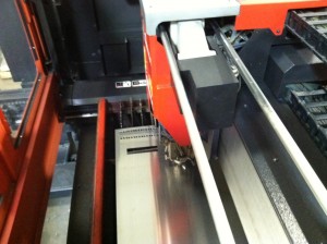
I wasn’t able to snap a picture of the machine actually bending up the cabinet but this is the machine that did it. It’s called a Panel Bender and works great for projects like this. The tooling is already installed and all you do is punch in a couple of numbers and off to the races. With this project and the time constraints, I bent every part by eye without using the CNC gauging system (takes longer to program the machine). I knew I was going to bend by eye so when I programed the part for laser cutting, I added little cutouts to physically show where I am going to place a bend. Line up the little cutouts with the tooling on the machine and it will put the bend within the tolerance that I need for assembly.

Here is the box after bending. I did a test fit by assembling all the parts. In the design I added 1/8″ diameter alignment holes. These holes when lined up and used with cleco pins (sort of like removable rivets) , will temporarily hold the panels together. This will allow me to either weld, spot weld or take one cleco pin out at time and replace it with an actual rivet.

Here it is all assembled and ready for paint. I decided on a black texture powder coat because it’s used often in the industry. Plus it hides my fat greasy fingerprints quite well.

And there she is… Ain’t  that a thing of beauty? I placed a 2U power strip just to illustrate that how universal it can be. Well that’s basically it. This little article is to show to process from the thought to design and from design to build. If I were to even build something like this, I would use thicker material and stick to the specs on the standard a little more closely. I would also add handles and reinforce the area where the handles are mounted.

Edit (9/30/2011): Here are some more photos (Click to enlarge)

Here is it at the house…

Here is a different view. On the bottom of the unit is a surge strip. When I fabricated I only made 3U panels so if I were to install devices that took up 1u or 2u then I would have a gap. So I made some additonal panels which haven’t been painted

Here is a upclose  shot that will show how the panels or modules are mounted. Depending on the design, some rack systems have sliding frame rails to extra weight support. The silver looking thing you see is actually a spring clip with a floating #10-32 nut. Back when these racks were first being designed, instead of using a square hole with a captive nut, they just had regular round holes that were drilled and tapped. Problem was if the threaded hole were to become stripped due to major use or misalignment, then the entire unit could be scrapped if it couldn’t be repaired. With the new system, you can just pop in a nut where ever there is one needed. If it gets stripped, just replace the nut!

Here a picture of the back of the unit. I created a 2X3″ in opening to allow cables to be routed through. When not in use, the gasket-ed cover can bolt right into place using two #10-32 screws that screw into pressed inserts on the main body to create a nice air/weather tight fit (even though the rest of the unit is not air tight).


Here it is with the radios installed. Considering this is the first time I actually got to physically handle the radios, everything lined up okay considering I was using the specs from a similar radio for it’s dimensions.

Overall it was a great build, I just might build another one and apply what I’ve learned on the new box If by some chance you have the chance to fabricate something similar, I would use 1/8″ Aluminum or 12ga (.105″) steel.


Radio Shack and Heathkit catering to the Amateur market?

I really hope so.

How many HAMs been to a Radio Shack recently? I have and it’s sad… really sad. Over the years, the component and DIY electronics section of Radio Shack kept getting smaller and smaller. The cell phone section kept getting bigger and bigger to the point where the electronics section is just a couple of cabinets and a 6ft wall of soldering irons (that are not good for SMD type soldering) and their assessories. And that’s even if your lucky enough to come  across a store with an electronics section. Now you go in looking for a component but instead you get hassled by the untrained staff to get you to buy a cell phone or batteries.  I am not old enough to know what it was really like but the Radio Shack catalog was what really got me interested in wireless communications. I was “oooh”ing and “awww”ing  over the things that were in there and I just had to get my hands on a CB radio.

The only thing I don’t get was WHY? Why did radio shack go the cell phone store route? Is it because of the high margin of cell phones, low overhead and back-end benefits to drive up profits? Damn right! IMO Radio Shack decided changing to a cellular phone store too late when there are already hundreds of  established stores within a 10mi radius that sell the same contracts, phone and accessories. That combined with the BIG box electronic stores, online electronic parts dealers (that dominates RSs markup) and the fact that most electronic devices are either no longer serviceable or too complicated  drove Radio Shack into a deeper hole which I thought were never going to dig out of. Heck, even The Onion made fun of Radio Shack.

In recent months, someone at Radio Shack finally kicked the board members (or whomever runs Radio Shack) in the ass and woke them up to a grim reality of what will happen to Radio Shack if they do not do something (Well, that’s what I imagine happened). Recently Radio Shack  is trying to dig and is going back to its roots and asked the DIY electronics community for help. Based on their answers, they actually posted a list with the Top 10 suggestion.  You will notice that HAM radio is listed and I hope that this is not a sales gimmick or some kind of publicity stunt or marketing ploy. At this point in time it looks like Radio Shack is joining up with Parallax (Company that manufactures and sells electronic kits) to release DIY electonic kits to the masses. I just hope with the quantity of product that RS is buying will lower the price.

I’m not sure if it’s directly related but a brand that almost every Amateur Radio Op knows is also throwing their hat in the DIY electronics game (again). HEATHKIT announced that they are getting back into the DIY Electronic kits for the consumer. They are starting out with a Garage Parking Assistant and a wireless swimming pool monitor kit with many other kits planned for the future. HEATHKIT is also asking for input from the DIY electronic community. So if you’re a ham (or not!), I would e-mail info@heathkit.com and let them know that there should be Amateur Radio related kits!

I never had the chance to actually build anything from Heathkit so I hope a something come across that I’m interested in learning! Maybe teach the kids when they are old enough about basic electronics.


Please stop the Noises! STOP!

Ever since I moved to my house I always had noise in my receiver. It wasn’t loud enough for me to care until now. For the past couple of months the noise has been real bad. Bad to the point where I didn’t even go past 20m (14mhz). I Figured when Field day comes around I will be able to see if its something with the radio. I turned on the radio at field day and the noise was still there. I was upset that I was going to have to ship my radio to YAESU for repairs. That is until someone turned off the light that was 3ft near the radio. THE NOISE IS GONE!!! YES!!! Found out that the cheap-o CFL Bulb (or it’s ballast ) was causing the RFI. I thought that this might be the same cause at my QTH. So after field day I setup back home and tried the radio without the lights. Noise was still there. Today I finally got off my ass and started to track down what was causing the RFI. I went to cellar and turned off all the circuit breakers except for the room which the FT-950 is in. The noise is still there. I unplugged everything in the room except the power supply and the Noise was still there. At this point I took a TV car battery (sealed) and hooked it up inside. The noise is GONE! With the process of elimination, I found out that the power supply was to blame. Back when I purchases the FT-100, I Moved the power supply close to the radio so I could power both the radios.

The power supply that was causing the RFI is the SAMLEX SEC-1223. I googled the model number and there were numerous sites that mention the RFI that power supply generates.

Two sites that stick out when it comes to getting rid of the noise are
http://www.n0ss.net/PDF

and

http://www.oz1db.dk/samlex/start_eng.html

ZL2DF used ferrite beads and ceramic disk capacitors  (about US$10 for part modification) placed right before the output terminals  and OZ1DB used two 1.5uf 100V Capacitors ( US$ 3) on the output terminals

Hello APRS My old friend.

I’ve come to talk with you again.


APRS – ™ By:  Bob Bruninga, WB4APR Http://www.aprs.org

Back in 2001 when I first got my license. I was interested in APRS because it was something I can do with my new license. I went as far as setting up a part time digipeater and after only a couple of months, the digipeater went down and lost interest in APRS because the cost of a GPS receiver at the time (even though GPS is NOT a requirement to listen or participate on the APRS network).
GPS receivers are a lot cheaper compared to 10 years ago and I have a old Garmin GPS-V lying around. So I figured this would be the perfect time to get back into APRS. For those who don’t know what APRS is, It’s Automatic Packet Reporting System which is an Amateur (Ham) based system for real-time communications of information using a digital protocal (AX.25). There are many possible things you can do with APRS. You can send (Short) text E-mail, SMS Messages,  send weather data (Which the NWS uses) and when hooked up to a GPS , will send position data.  I am not going to go into much detail because there are websites that are dedicated to APRS.
I am going to be doing a couple of things with APRS. One thing is that I am going to set up a part-time iGate (internet gateway) to make use of the frequency scanner and antenna that is not being used. Packets of Information received from the scanner (tuned to 144.39mhz) will be sent over the internet using the APRS-IS network so it can be databased and displayed on such websites as aprs.fi .

The other thing I want to do is location tracking. In order to do tracking you’ll need 2 or 3 things. You’ll need a GPS receiver that has an output for NMEA data, TNC (Terminal Node Connector) and a transceiver (VHF [144-148mhz] is Most used). As stated earlier, I have a Garmin GPS-V lying around and I also have a Kenwood TH-78A.  All that is missing is a packet TNC.  A Real TNC can cost $100+ and needs a computer. However there are units designed and built for APRS that will encode the data from the GPS to the AX.25 protocol and transmit the signal using the transceiver. I’ve purchased one of these units called ” TinyTrack3+” from a company called Byonics. It’s as basic as it gets. You can either buy it as a kit or assembled, with or without a GPS Receiver, with or without cables for your transciver or with or without cables for various GPS models.  I ended up going with a solder and assemble your self kit without any extra cables because I wanted to invest the least amount of money in it as possible.

Here is the kit as you would get it in the mail. It comes with the componets, board, case and instructions.

Here is the board soldered up. I used a 35W Pencil type soldering Iron. I filed the tip a little bit to assure that solder flows to the tip. It took about 1/2 to 3/4 of an hour to solder. If your new to assembling boards, I would go to the Byonics website and download the manual because the online .pdf manual will cover the assembly and everything else in great detail. As long as you follow the step by step instructions, it will turn out great. For newbies make sure the diodes are going in the right direction, LEDs in the right direction and make sure the notch (little cutout) is aligned with the silk screen image.

Now that board is done, time to make some cables! (Since I didn’t order any)

Here is the cable all assembled! It’s a DB-9 Connector  (Radio shack P/n: 276-1538 US$2.69) , Pos and Neg power cords with Anderson power poles attached so it could powered by many different sources (7-35vDC), Sacrificed  speaker microphone from the Wouxun for its cable, Ferrite Core choke (Optional, Radio Shack P/N: 273-105) and the DB-9 Case (Radio Shack P/n: 276-1539 US$2.09). I Got the wiring diagram from the  Byonics website and took about 1/2 hour to make which ended up costing me around $5 since I already had the cable, choke and power connector

Just an FYI, I sacrificed a speaker microphone from my Wouxun. Power-Werx which distributes Wouxun products (as well as the power poles), has the exact same cable for this application for sale on their website. They also have a similar one but with a cigarette lighter plug (Both for US$20). Byonics also sells cables for this and many different radios. Also note that that wouxun speaker mic layout is the same for kenwood HT’s!

After you assemble the tracker and the cable. Apply power to unit and hopefully it comes to life by flashing the yellow and green LEDS three times. Only thing left to do is to program the tracker using your computer. This point it can get tricky. The TinyTrak3 needs a NULL modem cable (Or adapter) to program it and possibly a gender changer. I found that I didn’t have a null modem cable, all I have are straight through cables. Since I didn’t want to wait for an adapter I made one from old computer parts lying around my house

Here is the cable that I made from parts out of an old 486 that I had in the attic. It’s not pretty or rugged enough for daily use but once you program the Tracker and are satisfied with the operation then you will most likely not have to program it again.

Here is the complete setup. Right now I have the unit running off a 9V battery. I also used a cigarette lighter plug with power poles connected to it. Depending on how you programmed the tracker, It will only send when there is data from GPS. There are limitless things you can do with this setup. For SOTA members (Summits On The Air), They can bring this along with them so others can see their progress in their hike. If you helping out in a public service or public events which ham radio operators are helping, you can show your location to HQ without even telling them. It makes things a lot easier.

Here is my first track. I learned a lot when doing this. I found that my handheld in the truck has a hard time communicating with the digipeaters in the area. I might purchase a small 1/4″ wave mag-mount  or a duplexer and switch to my dual band antenna for when I am running APRS in the truck.

Modifications

I added things to the Tinytrak3+ which I think will make it better for me to run. If I had to be really critical about the tracker is that the DB-9 connectors did not come with mounting screws. The first test out with my truck the power/radio connector became loose and eventually lost power to the tracker. To fix this I went scavenging parts off  a old computer.

Now I can secure both the power and GPS connections. The screws came off the LPT and monitor ports of an old mother board. There is a small amount of space between the back plate of the connector and the board. So I had to grind down the bolts and nuts so It would not touch the board.

Another issue that might come is when I am portable (walking). More likely the power source for the tracker for this purpose will be a 9V battery. The tracker with all the LEDS running will consume around 18.6ma which means a 9V battery (.370Ah avg) could possibly last for about 9-12 hours (60% discharged). If  you turn off the LEDs, the power consumption is 6.6ma. On a 9V battery, the tracker could last around 30 hours. The TinyTrak3+ can run without the LEDS by cutting a lead (tells you how in the directions). If you using a high-capacity 9V (.580Ah)with no LEDs it could last for more than 50 hours so it might be beneficial to cut the lead and add a jumper. The down side is that you will not know the status of the Tinytrak.

So what I did is cut the lead on the board and installed a bridge (shown in the picture above with the blue jumper). When jumped the LEDs are operational.
Also pictured are 2 bridges installed (on the left side) for jumpers J5 (outside pair) and J6 (inside pair). If J5 is jumped it will switch to what was programed in the secondary tab in the program (Program 2) . This would work great for an event which required either a different call and/or different settings. After the event, you can switch back to the primary settings. If J6 is jumped it will send a signal to power on the transceiver. This would involve another board with a relay to put power into the transceiver or modifying the transceiver. I don’t plan on messing around with it any time soon but since I am soldering on jumper bridges, why not.

Overall it was a really great build and I am having a blast with APRS. My plans are to find a way to make it all fit into a nice tiny package that I could carry when hiking or driving.

73 and thanks for reading!


Homebrew GMRS 3 Element Yagi

Since I’ve built a ton of J-Poles and wire Antennas, I’ve wanted to build something different. I decided on a 3 element YAGI built for GMRS that is directly fed with 50ohm coax. After a couple of failed yagis and the help of another ham on QRZ.com forums, I finally built a Yagi that works! The reason I’ve chosen a Yagi built for GMRS is due to the ultra high frequency, which ends up being a small antenna. If I were to mess up (Which I did), the material cost would be low. I also wanted to use it on a GMRS repeater in the area.

The first Design I used is with a Web Site that has a Java base applet to design the Yagi, After getting all the Dimensions from the website, I went to work building the antenna. After everything was done, I learned two things. One is that my drill press does not drill straight (90 Degrees) through the tubing. The other thing is that when I hooked up the antenna to a simple SWR Meter, That didn’t work either (Pegged the Meter). At this point I got frustrated  and posted my issue on QRZ.com. A Ham by the call of WB3BEL (Harry) took my dimensions (That I got from the applet) and plotted my antenna into 4NEC2 software (Like EZNEC but freeware) and it would not work for the center frequency of the GMRS Band (or any part of the GMRS band).
WB3BEL actually re-designed the antenna to where it would work so I give him credit and major thanks for help. I took his Dimensions, Modeled the antenna for fabrication and built the antenna. I Hooked up the antenna to a transceiver and SWR meter and got a 1.2:1 SWR and a 1.5:1 SWR on the outsides of the GMRS band. The Design is calculated to yield 7.5Dbi of Gain. Considering connector and cable loss (Lets say 4Dbi using 50ft RG-213 W/ 3 SO-259 Ends and a Barrel Connector) still yields gain of around 3.5Dbi which is not too bad.

Here is rendered Image of the Antenna. The elements are Insulated from the boom using plastic shoulder washers for the Reflector and director. The Driven Element is insulated using a 0.750(OD)X.375(ID)X1.5″(L) Plastic spacer. Since the elements are going THROUGH the boom, It will make the elements electrically shorter so you have to compensate for the loss by adding 0.279528″ (7.1mm) to the element to correct the effect (Boom correction). The elements are secured using #8-32 Screws screwed to the boom. The screws are also insulated from touching the boom. The screws do not make any significant changes to radiation pattern of the antenna as long as it’s insulated from (not touching) the boom. I did notice that the screws actually lowered the SWR a tad which is great.

I didn’t add a matching network to the antenna because I wanted an easy to build and assemble antenna which is the entire point of this article. The antenna is fed using RG-213 Coax with terminals soldered to the core and shield. I tried to keep everything as short as possible because this and the ring terminals effect the performance and SWR of the antenna.

Here are a couple of screen shots from the antenna software that show the Radiation Pattern and gain. Nothing special here.


Here is the calculated results for the SWR of this Yagi. Please note that it’s in the ball park. By adding screws, coax leads and the ring terminals, it could or will effect the final pattern and/or performance of the antenna.


Here is a SWR Shot. As you can see, I don’t have a very good meter. I would like to buy a HF/VHF/UHF Antenna analyzer for my Antenna builds but I don’t think that will happen in the near future.


Here is the complete Antenna.
Overall it was a fun little project. It took a short time to build and it’s a great directional antenna with some gain to help your signal on GMRS reach its destination.

Continue reading if you want to build this antenna.

Continue reading “Homebrew GMRS 3 Element Yagi”

HCRA Field Day 2011

This year I participated in Field Day with the Hampden County Radio Association. Instead of dropping by a site and using their equipment, I decided to offer up my equipment for use as the “HF DIGITAL” station. Other than a couple of software issues, the Digital station was a success with over 170 contacts.

Here are the pictures I’ve taken from Field Day

Check out Hampden County Radio Association’s Website for information about Field Day.
Continue reading “HCRA Field Day 2011”